For the past several Field Days, I have enjoyed operating with my friend Ian, W4NAI. Last year on Field Day we ran into issues with multiple radios side by side. The interference was really bad on 20 meters from another radio on 40 meters. This year we wanted to get a jump on it as we have a unique Field Day location planned. After doing a bit of a survey, I landed on the kits from VA6AM. While I could buy filters, I find it more fun to construct the filter myself. In this kit alone I’ve greatly improve making tight wraps on toroids and learning how to fix issues.

I had a few project boxes and standoffs already so I started off with the mechanical layout. I used the PCB to figure out the mounting holes and a melted SO-239 for the holes on the coax connections. To get the hole large enough, I used a step bit. It should be noted that the enclosure is the ground and is connected to the PCB by the standoffs, so it was critical to have those be conductive.
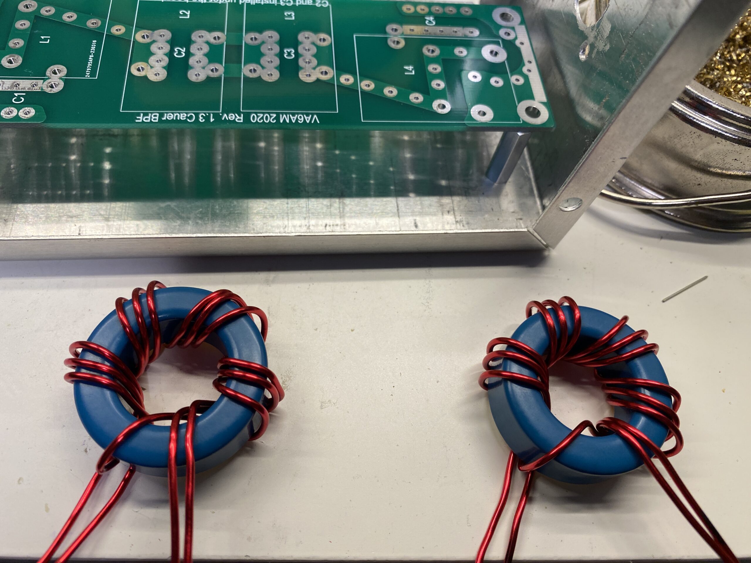
The instructions started off winding the input/output toroids. These are unique in that they are actually a transformer and the secondary coil has a proportional number of wraps to the first.
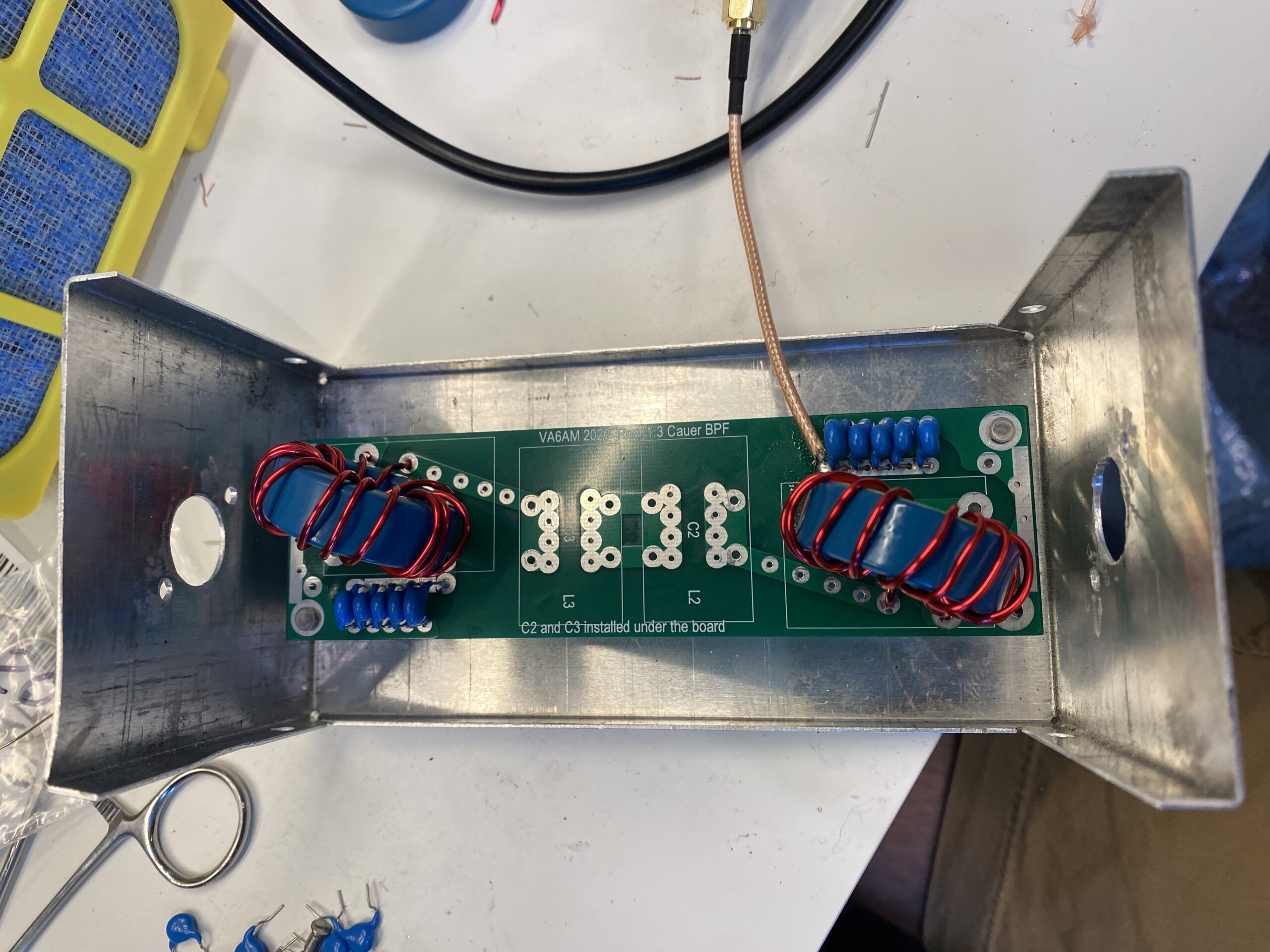
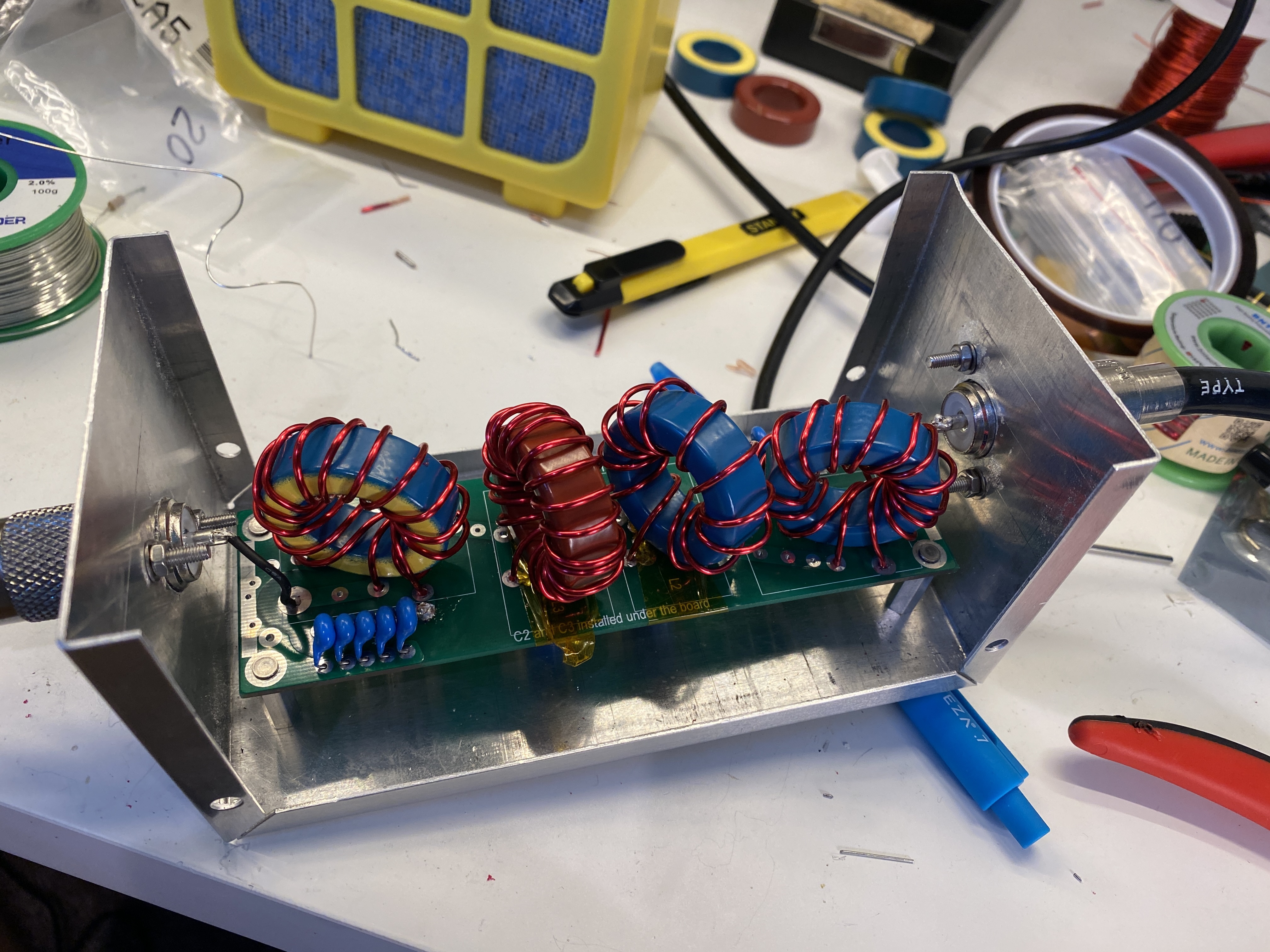
With the toroids made, I soldered on the input/out put capacitors and mounted the toroids. VA6AM has you tune the circuits to the same frequency. This is done by soldering on a bit of coax and reading it on the VNA. I ended up spreading the coils a bit for them to match and spent a while playing with them. If you look at the photo, you can see there wraps are not super tight. In the end, that cost be a bit of insertion loss (about 0.2 dB) and out of band attenuation (about 6 dB). The filter pictured is for 20 meters, but the 40 meter filter had better results (about 0.4 dB insertion loss and my out of band attenuation was on par with expected).
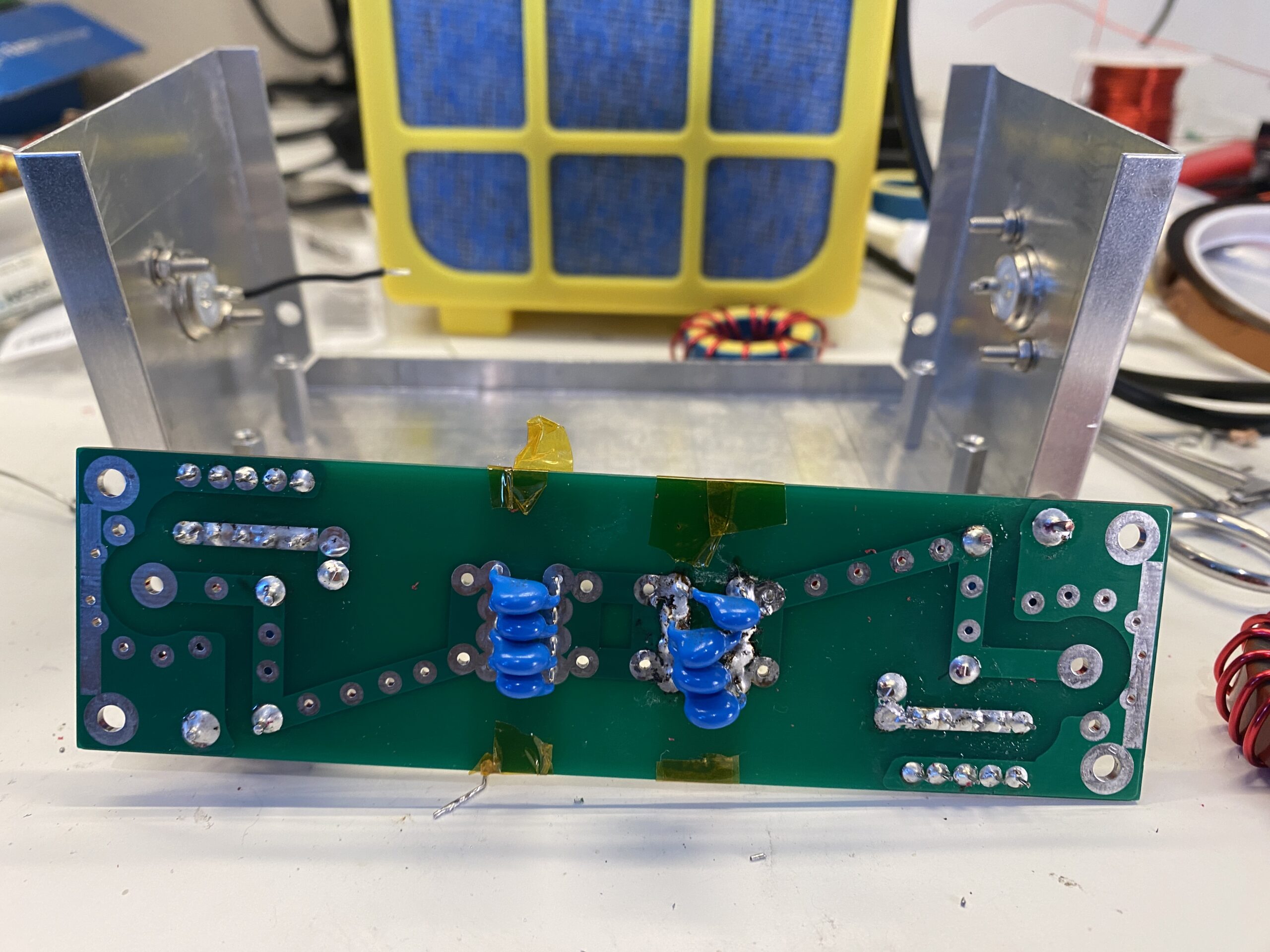
My construction wasn’t perfect. I accidentally mounted one set of capacitors wrong and had to fix it. It isn’t pretty, but it is functional. The good news is I only made this mistake on one set of capacitors and made sure I was correct on the remaining ones.
You might notice some Kapton tape in the photo. I used the tape to protect the toroids that sit above the solder joints from getting scratched. I use Kapton tape a lot with 3D printing, but it is also helpful for electronics as it resistive to heat and durable.

The final assembly of the filter was a success. I achieved less than 0.5 dB of insertion loss on both filters across the band. I saw at least 53 dB of rejection on adjacent bands. So these two filters achieve about 100 dB of attenuation between 20 and 40 meters. Testing with the radio, noting got hot with my usual 35 watts of FT8 or 100 watts of SSB and the SWR was 1.2 at the worst, so very happy with how everything came together. I labeled all the details on the project boxes for reference so we know what to expect on Field Day.
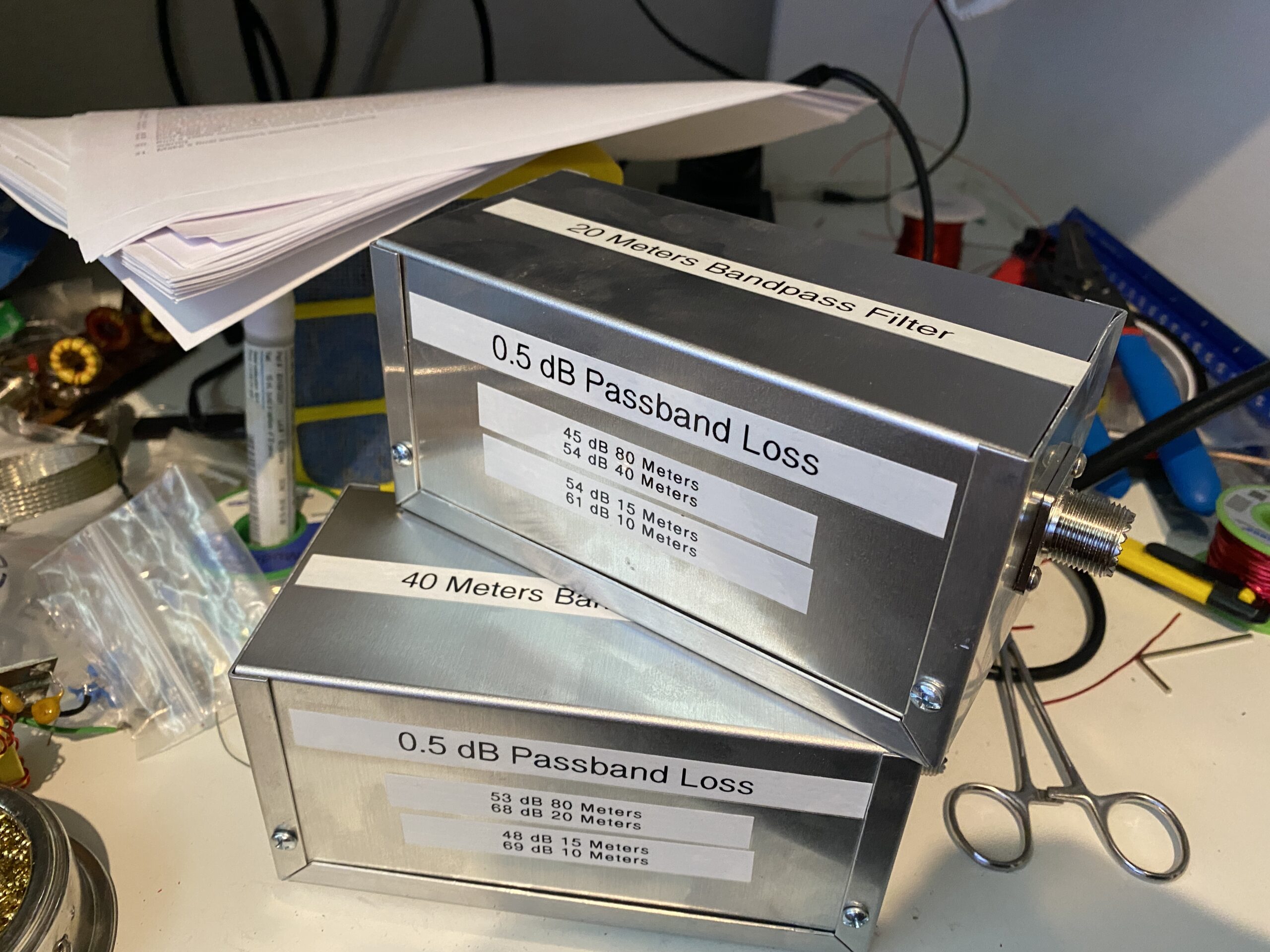
With the success of the these two filters, I’ve order 10, 15, and 80 meter kits to assemble before Field Day!
